Special enameled wire is resistant to Freon-22 corrosion and can be used as winding wire for motors in fully enclosed or semi-enclosed refrigeration compressors. The refrigerant can flow directly through the inside of the motor without the winding wire being corroded. It is suitable for refrigerators, window air conditioners, constant temperature and humidity equipment, air coolers and other products. Therefore, before leaving the factory for use, it is necessary to test the refrigerant resistance of enameled wires.
The following are experiments conducted on refrigerant-resistant enameled round wires:
General
1.This test is applicable to enamelled round wire.
2.Resistance to refrigerant is expressed by the quantity of matter extracted from the coating of the wire and by the breakdown voltage after exposure to a refrigerant.
3.The data in this test method apply to monochlorodifluoromethane (refrigerant R22). When these other refrigerants are used, it is important for safety reasons to observe the critical data for these refrigerants and to comply with the revised test conditions during operation of the pressure vessel.
4.Refrigerants like monochlorodifluoromethane and rinsing fluids like trichlorotrifluorethane (refrigerant R113) are ozone depleting chemicals (ODC). Refrigerant and rinsing fluid are agreed upon between customer and supplier.
Principles and required equipment
A siphon cup containing the wire sample is placed in the pressure vessel. The extractable matter is determined after exposure of the wire sample to the refrigerant under pressure and at elevated temperature.
The following equipment shall be used:
1. Siphon cup according to Figure 2, Refrigerant extractable test siphon cup, of 450 ml volume up to the siphoning level. Height of cup: (82 ± 5) mm; Diameter of cup: (84 ± 5) mm; Diameter of tubing: (5 ± 1) mm;
2. Pressure vessel of 2 000 ml volume with an internal diameter of approximately 100mm
and a pressure capacity of 200 bar (20 MPa), preferably of unwelded construction and
provided with a controlled heating system;
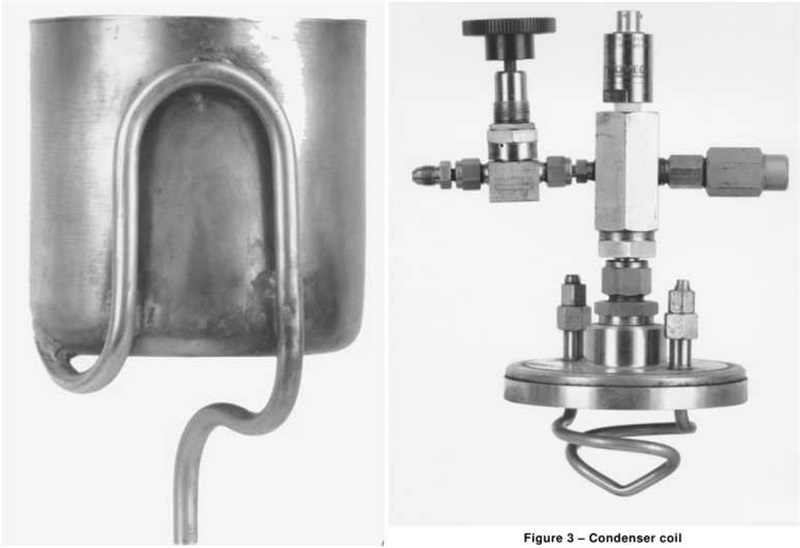
3. Top closure of the vessel containing a condenser coil according to Figure 3;
4. Oven with forced air circulation.
Specimen: Eight wire samples each containing (0.6 ± 0.1) g of insulation shall be wound into coils of 70 turns. The specimens shall be degreased and conditioned in an oven with forced air circulation at (150 ± 3) °C for 15 min. After 30 min cooling, the eight specimens shall be weighed together to the nearest 0.000g, resulting in the total initial mass M1.
Procedure
1. The eight specimens shall be placed in the siphon cup, which is suspended (25 ± 5) mm below the condenser coil on the pressure vessel cover. The pressure vessel shall be assembled and charged with (700 ± 25) g of distilled refrigerant free from lubricant. The condenser water supply and drain line shall be connected and the pressure vessel shall be heated by means of a controlled heating system with the temperature set to (75 ± 5) °C or a lower temperature if required to comply with the conditions of the following paragraph relating to critical pressure. The water flowing through the condenser shall be adjusted to maintain a reflux rate of 20 to 25 discharges per hour from the siphon cup. The extraction period shall be 6h.
2. The pressure in the vessel shall not exceed 75% of the critical pressure of the refrigerant chosen. Therefore, prior to use, the over-pressure control valve shall be checked to ensure its proper functioning. The heating system should be automatically deactivated if the pressure exceeds 75% of the critical pressure of the refrigerant chosen or if the water flow through the condenser coil is interrupted.
3. At the end of the extraction period the pressure vessel shall be cooled. The refrigerant shall be removed from the pressure vessel and recovered using suitable means such as a refrigerant compressor and recovery system. The pressure shall be released and the pressure vessel opened.
For the following operations, the rinsing fluid shall be distilled before use.
1. The specimens and siphon cup shall be rinsed with the agreed rinsing fluid, the rinse poured into the pressure vessel and the walls of the pressure vessel washed with two successive rinses each of 100ml of rinsing fluid. The fluid shall then be evaporated to (5 ± 1) mm from the bottom of the pressure vessel and recovered in a safe manner.
2. The liquid sample shall be transferred to a pre-dried tared aluminium weighing dish and the pressure vessel rinsed with 15ml of rinsing fluid, which is transferred to the dish and then evaporated to dryness at (150 ± 3) °C for (60 to 65) min. The weighing dish shall then be cooled to room temperature in a desiccator. The dish with the residue shall be weighed to the nearest 0.0001g and the original tared mass of the same dish subtracted. The difference is the total residue mass M2 of the matter extracted from the eight specimens.
3. The insulation on the coils shall be removed by suitable chemical means not affecting the conductor and the bare conductors shall be dried at (150 ± 3) °C for (15 ± 1) min and cooled to room temperature in a desiccator. They shall be weighed to the nearest 0.0001g and the mass of the eight conductors together is the total conductor mass M3.
The Result extractable matter shall be determined according to the following equation:
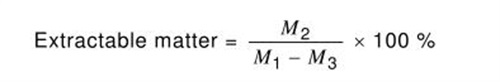
One test shall be made. The masses M1 , M2 , M3 , the refrigerant, rinsing fluid, temperature, pressure of the pressure vessel and the percentage extractable matter shall be reported.
Breakdown voltage test
A specimen prepared according to 4.4.1 of IEC 60851-5:2008 is placed in a pressure vessel according to 4.3.2. The breakdown voltage is determined after exposure of the specimen to the refrigerant under pressure and at elevated temperature.
1. The specimen shall be conditioned in the oven (150 ± 3) °C for 4h and then placed in the pressure vessel, which shall be assembled and charged with (1400 ± 50) g of refrigerant. The pressure vessel shall be heated according to 4.2.4 but for a period of (72 ± 1) h.
2. At the end of the exposure period, the pressure vessel shall be cooled and discharged as described under 4.2.4. When the pressure inside the tube is less than 2 bar (0.2 MPa) absolute, the pressure vessel shall be opened and the specimen, within a period of 25s to 30s, transferred to the oven at a temperature of (150 ± 3) °C. The specimen shall remain in the oven for (10 ± 1) min. After the specimen is removed from the oven and allowed to cool to room temperature, the breakdown voltage shall be determined according to 4.4.1 of IEC 60851-5:2008.
3. Result:Five specimens shall be tested. The five individual values shall be reported.